Wall Panels
The wall panel element allows you to easily model walls for in plane and out of plane loads. Wall panel data may be viewed and edited in two ways: graphically in the Wall Panel Editor or in the Wall Panels Spreadsheet.
Drawing Wall Panels
There are several graphic-editing features that make the creation and modification of models quite easy. Use the Insert and Modify menus or the Drawing Toolbar to use these features in the model view. To create new wall panels, you can draw them using a drawing grid or draw "dot to dot" existing joints. Once you have created these items you may use other graphic features to apply loads and set boundary conditions.
You can set many of the wall panel properties up front or you can modify these properties after you draw them. Modifying properties is discussed in the next sections. See the Wall Panels topic for information on wall panels and their properties.
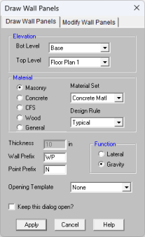
The Draw Wall Panels  button lets you graphically draw wall panels in your model. Enter the appropriate wall panel parameters, click OK and draw wall panels between existing joints or on the drawing grid. You will also notice that the coordinates of the joint or grid point that is closest to your cursor are displayed in the lower right hand corner of the model view. The new wall panels will be shown on screen and will be recorded in the Wall Panels Spreadsheet.
To actually draw a wall panel, you have two options. One way is to modify your Drawing Grid according to how you wish to lay out your wall panels and use the Create Wall Panels by Clicking on Grid Areas option. Wall panels can then be created by clicking in the grid areas formed by the intersecting grid lines. As you click on an area, a wall panel will automatically be created in that area. The second option is to create wall panels by drawing them one joint at a time. First click on the grid point or joint that you want to be the "A" joint for the plate, then the "B" joint, "C" joint, and "D" joint in either clockwise or counter-clockwise order. The wall panel will "stretch" like a rubber band as you draw from joint to joint.
Note:
- You must draw wall panels rectangular.
The parameters shown are the same parameters that you would enter on the Wall Panels Spreadsheet.
-
If there is not a model view already open then click  on the RISA Toolbar to open a new view and click
  to turn on the Drawing Toolbar if it is not already displayed.
- If you are not drawing between existing joints, you will need to create a drawing grid or define joints on the Joint Coordinates spreadsheet.
- Click the Draw / Modify Wall Panels
 button and select the Draw Wall Panels tab. Then set the wall panel properties.
- Click Apply to start drawing wall panels by connecting grid points or by clicking on individual grids.
-
To stop drawing altogether right click or press the Esc key.
- To draw more wall panels with different properties, press CTRL-D to recall the Wall Panel Properties settings.
- You may also specify or edit wall panels in the Wall Panels Spreadsheet.
- You may also view and edit wall panel properties by double-clicking on a wall panel.
- You may undo any mistakes by clicking the Undo
 button.
- Drawing clockwise or counter-clockwise determines the panel's local axes directions. See Wall Panel Local Axis for more information.
- You can choose elevations where the wall panels begin and end if you have multiple floor levels. This allows you to have continuous wall panels along a given height.
- When graphically drawing wall panels, it is irrelevant which floor you are on when you are drawing. You can draw wall panels on floors that are not in the current view. Thus, you need to be careful when drawing wall panels that you have the right floor to floor levels for your wall panels.
- In the Draw Wall Panels tab, you can select an Opening Template to be applied to the wall panel you are drawing. See Wall Opening Template for more information.
Modifying Wall Panels
There are a number of ways to modify wall panels. You may view and edit the member data in the Wall Panel Spreadsheet, you may double-click a wall panel to view and edit its properties, or you can use the Modify Wall Panels tool to graphically modify panels.
The graphical Wall Panel Modify tool modifies the properties of wall panels that already exist in the model. To use this tool, specify the properties you want to change and then select the wall panels that you want to apply these changes to. Wall panels can be modified one-at-a-time by selecting the Apply Entries by Clicking option. This will change the mouse cursor to a modify tool which applies to any wall panels which you click on. A group of selected wall panels can be modified all at once by using the Apply Entries to All Selected option. See the Graphic Selection topic for more on selecting.
The parameters shown are the same as those used to define new wall panels.
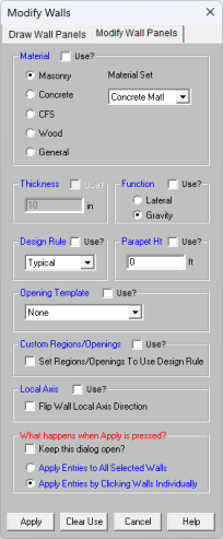
The Use? check boxes next to the data fields indicate whether the particular parameter will be used or not when the modification is applied. If the box next to a field is checked, that parameter will be applied to any selected wall panels. If the box is NOT checked, the parameter will NOT be applied, even if a value is entered in the field. This allows you to easily change one or two properties on wall panels without affecting all the rest of the properties. Note that if a no value is entered in a field (i.e. the field is blank) and the corresponding check box is checked, clicking “Apply” will have the effect of clearing the data for that field.
- If there is not a model view already open then click on the RISA Toolbar to open a new view and click to turn on the Drawing Toolbar if it is not already displayed.
- Click the Draw / Modify Wall Panels
 button and select the Modify Wall Panels tab. Then set the parameters for the new wall panels. Check the Use? Box for the items to apply.
- You may choose to modify a single wall panel at a time or to an entire selection of wall panels.
- To modify a few wall panels choose Apply Entry by Clicking Items Individually and click Apply. Click on the wall panels with the left mouse button.
- To modify a selection of wall panels, choose Apply Entries to All Selected Items and click Apply.
- To modify more wall panels with different parameters, press CTRL-D to recall the Modify Wall Panels settings.
- You may also modify wall panels in the Wall Panels Spreadsheet.
- You may undo any mistakes by clicking the Undo
 button.
- The thickness option is only available if you are choosing a General or Concrete material. Wood and Masonry require you to change their thickness in the Design Rules spreadsheet.
- Only walls that exist on the currently viewed floor will be modified if "Apply to All Selected.." is chosen.
- For existing models of version 5.1.1 or earlier, all wall panels will be brought in using Custom regions/openings. Here we provide an option that will reset all wall panels to base their design on the Wall Design Rule.
- In the Modify Wall Panels tab, you can select an Opening Template to apply to selected walls. See Wall Opening Template for more information.
Wall Panel Spreadsheets
Another way of editing wall panels is through the Wall Panel Spreadsheet. This spreadsheet is accessible through the Data Entry Toolbar and includes data on two tabs: Primary and Advanced.
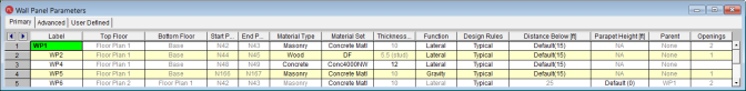
The following data columns hold the primary data for the wall panels:
Wall Panel Labels
You may assign a unique label to any or all of the wall panels. You can then refer to the wall panel by its label. Each label has to be unique, so if you try to enter the same label more than once you will get an error message. You may relabel wall panels at any time with the Relabel Wall Panels option on the Tools menu.
Top/Bottom Floor
This defines what level in the structure the wall panel starts and stops. This can be edited in this window.
Start/End Point
This shows the start and end joint that defines the extreme ends of the wall. This is for display only. You must delete and redraw wall panels to modify these values.
Wall Panel Material Type and Material Set
The material set label links the wall panel with the desired material defined on the Material Spreadsheet.
Note
- Currently wall panels can only be made up of concrete, masonry, wood, or general materials.
Wall Panel Thickness
The thickness field on the Wall Panels Spreadsheet is the thickness of the element. This thickness is constant over the entire element. Note that the thickness for Masonry and Wood wall panels are set in the Design Rules spreadsheet. For concrete and general material walls the value is defined here.
Wall Panel Function
If the function is defined as Lateral, then this element will be brought into RISA-3D for the lateral design. If the wall panel is defined as Gravity, then it will only exist in RISAFloor.
Design Rule
This allows you to choose a specific design rule from the Design Rules spreadsheet. The design rule is where you can specify very detailed information for the wall.
Distance Below
This value allows you to define the height of the lowest level walls in the structure. This allows you to have control over bottom elevation of each individual wall panel. By default we will use the Splice Distance Below value from the Floors spreadsheet. If you change this value and want to go back to the default, simply delete the value.
For wall panels that do not sit at the base, this field is not used and will be grayed out.
Parapet Height
This value allows you to define the height of a wall parapet. The Parapet Height entry will be used to calculate the self-weight of the parapet for loading and seismic weight calculations. It will also physically bring the parapet into RISA-3D on beam-supported floors (not for slab floors).
The Floors spreadsheet defines a default parapet height that will update all walls simultaneously, thus that is the primary place to update your parapet heights. You would only update them in the Wall Panels spreadsheet if you had differing height parapets around your roof level.
- Wall parapets can only be defined at the top of a wall stack and must be collinear with a deck edge.
- Wall parapets can not be added above slab floors. The deck edge defines the parapet perimeter in that case.
- Edits to the Parapet Height must be input greater than the Parapet Height Default from the Floors spreadsheet.
- See the Load Generation - Wind Loads topic for the effects on wind load calculations.
Parent
This column will show if there is a parent wall panel to the current wall panel. See Parent/Child for more information.
Openings
This column shows how many openings are present in a wall panel. The cell will be blank if a wall panel does not have any openings. Clicking in the cell will open the Wall Panel Editor where you can review and make modifications to your openings.
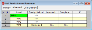
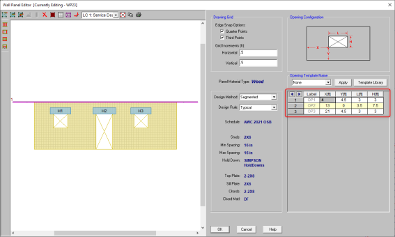
Design Method
This is a column specific to wood wall panels and allows you to choose which design method you choose to work with: Segmented, Perforated or Force Transfer. See the Wood Wall Panels topic for more information. These design methods are not applicable for concrete, masonry, or general wall panels.
Note:
- Currently, wood wall panel design is only available for NDS design.
Icr (In Plane and Out of Plane)
These values are considered for both masonry and concrete wall design and allow you to modify the stiffness of the wall for cracking considerations. This value will be multiplied by the Igross of the wall.
Masonry Walls
By default (if left blank) the program will use a value of 0.50 for both In-plane and Out-plane Icr Factor. This value comes from Section 3.1.5.2 of the ACI 530-11 code. If you have performed a cracked section analysis or want to override this default you can input it directly here.
Concrete Walls
By default (if left blank) the program will use a value of 0.70 for In-plane Icr Factor and 0.35 for Out-plane Icr Factor. These are the minimum factors for beams (Out-plane) and columns (In-plane) per ACI 318-14 Section 6.6.3.1.1 (ACI 318-11 Section 10.10.4.1). If you have performed a cracked section analysis or want to override this default you can input it directly here.
For service
level analysis, the level of cracking will be significantly less. Therefore, the stiffness used in your analysis should be representative
of the reduced loading and reduced cracking. Per the ACI 318-14 Section R6.6.3.2.2 (ACI 318-11 Section R10.10.4.1), the program will account for this increased stiffness by applying
a factor of 1.43 to the cracked section properties for any load combination
that has the “Service Load” flag checked on the Design tab of the Load
Combinations Spreadsheet
Note:
- This factor will only be used if the Use Cracked Sections checkbox is checked in the Concrete tab of Model Settings.
- This factor (or 1.43*Icr) can not be greater than 1.0.
K Factor
This is the effective length factor and is available concrete, masonry and wood walls. If left blank this will be taken as 1.0.
- For masonry this factor affects ACI 530-11 equations 2-16, 2-17, 2-19, 2-21, 2-22, 3-11, 3-12, 3-18, 3-19, and Section 3.3.5.3.
- For wood this affects the Cp factor calculation (specifically FcE) for wood compression capacity for both studs and chord design.
Inactive
This column allows you define a wall panel as inactive or excluded. Please see the Inactive and Excluded Elements for more information.
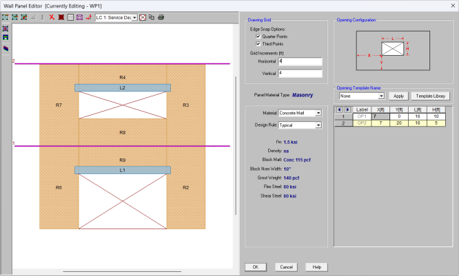
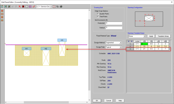
Wall Panel Editor
The Wall Panel Editor allows the user to edit the detailed properties of a wall panel including openings and regions. This dialog also gives design options and details for the specific panel and is accessible by double-clicking on an existing wall panel.
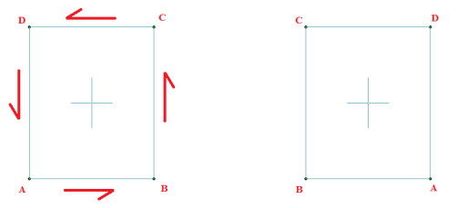
If the wall panel is drawn clockwise it will be drawn with the panel's local x-axis going from left to right. If drawn counter-clockwise the panel's x-axis will go from right to left and is presented here as though you are looking at the back side of the panel.
Note:
Creating Openings
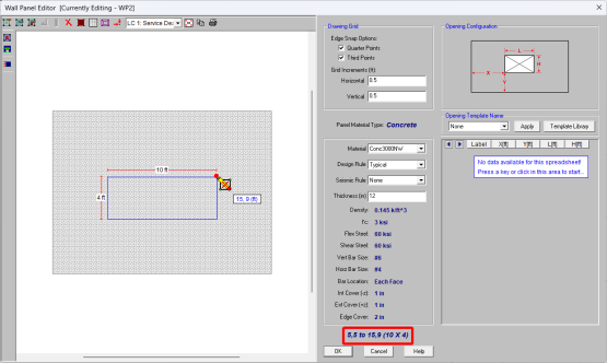
Within the Wall Panel Editor, you have the option of adding rectangular openings to the wall panel. To draw an opening, select the Create New Openings  button and then select two grid intersections which make up the two diagonal corners of your opening. Notice that you can view the relative coordinates at the cursor location by hovering over a snap point. The opening dimensions are displayed based on the first click and the current location of the cursor. The relative coordinates and opening dimensions are also displayed in the lower right portion the Wall Panel Editor window.
To exit this tool right-click your mouse.
You can also create openings using the spreadsheet provided in the Wall Panel Editor. Similar to other spreadsheets, you can add, delete, and modify the geometries of your openings. The variables used for defining openings are shown in the figure in the upper right portion of the window. The location of the opening (X, Y) is defined from the lower left corner of the opening to the lower left corner of the wall panel. Spreadsheet operations such as Fill Block and Math on Block can also be used within the spreadsheet to quickly modify multiple cells. These spreadsheet tools can be accessed by right-clicking in the spreadsheet. See Spreadsheet Operations for more information.
If you have invalid openings, which include:
- Openings beyond the wall extents
- Openings overlapping with another opening
- Openings overlapping with an existing wall region
- Openings spanning over a diaphragm
- Openings created on an inactive floor
The program will display red text in the spreadsheet for the entries associated with the invalid openings.
When you click OK, the program will display an error message asking you to fix the invalid wall openings before they can be applied to the wall panel.
Note:
- Drawing an opening in a concrete wall will create a lintel above the opening. We will not design the lintel but we will give analysis results. See the Concrete Wall - Design topic on lintels.
- Drawing an opening in a masonry wall will create a lintel above the opening. For more information on defining lintel geometry and design properties, see the Masonry Wall - Design topic on lintels.
- Drawing an opening in wood wall will create a header above the opening. For more information on defining the header properties, see the Wood Wall - Design topic on headers.
- Drawing an opening in a general wall panel, there is no header/lintel automatically created. The general wall panel is given as an option for analysis only.
- Openings must be drawn greater than 3 inches away from wall edges.
Creating Regions
Within the Wall Panel Editor, you also have the option of creating different rectangular regions within your wall panel. Regions are used to further define areas of your wall panel for use in analysis/design. If you do not specify a region in a wall panel without openings, then the entire wall panel will be considered a region.
To automatically draw regions you must first have your openings input. Once you have that you can click the Generate Wall Regions Automatically button and the program will define regions as we would expect a user to want them.
Note:
- If the regions defined are not located correctly by the generator, you can delete the generated regions with the Delete
 button and redraw them manually. See below for more information on this.
To manually draw a region, select the Create New Regions  button and use your cursor to select two grid intersections which make up the diagonal corners of the region. Similar to wall openings, local coordinates and region dimensions will be displayed in the lower left corner in the Wall Panel Editor. To exit this tool right-click your mouse.
Note:
- Results are only presented for full-height regions. For a gravity analysis this is generally sufficient. If a gravity analysis is required for a non full-height region you must transfer this wall to RISA-3D.
- For masonry wall panels, there is a region editor that allows you to define design properties for the region. Double-click inside the boundary of the drawn region to open this editor. See the Masonry Wall - Design topic for region information. Note that design and analysis results are displayed by region.
- For wood wall panels the design and analysis results are displayed by region.
- For concrete wall design, the program will automatically create regions at solution around openings. If there are floors/diaphragms that cut through your wall, then separate regions/designs will be created above and below the floors/diaphragms.
- For general wall panels we will not do any design for you. However, you can lay out your regions so that your analysis results will allow you to design your general wall panels much more easily.
Drawing Grid
The drawing grid, which appears in the upper right corner of the Wall Panel Editor screen, gives the user options for drawing within the Wall Panel Editor window. The options include:
Snap Options allows you to provide snap points at the edges of the wall panel at quarter and third points.
Grid Increments allow you to set a drawing grid within the Wall Panel Editor separate from that in the main model view that you can snap to when drawing openings and regions. This field can work in two separate ways:
- A single increment: If you put a single value here (0.5 ft for example), then this increment will be used across the entire wall until the end of the wall is reached.
- Multiple input increments: If you have specific locations you wish to define you can use this field to place exact grid points. Commas are used to delineate different grids and @ symbols can be used to apply the same increment multiple times (5, 10, 2@8, 3 for example). If you place multiple increments in and you are not yet to the end of the wall then the last increment defined will be used until the end of the wall is reached.
View Controls
In addition to the wall panel editing tools, the Wall Panel Editor window includes the following view controls:
Delete allows you to delete openings, regions or boundary conditions from the wall panel.
 Render will turn rendering of the current model view on or off, depending on the current setting.
 Nodes will show any nodes that fall in the plane of the wall panel and allow you to snap to them when drawing regions or openings.
 Drawing Grid will turn the display of the Drawing Grid on or off, depending on the current setting.
 Diaphragm Display will turn the display of the Diaphragms on or off, depending on the current setting.
 Loads will turn the display of the wall panel loads on or off, depending on the current setting.
 Redraw Full Wall View redraws the wall panel to fit within the Wall Panel Editor window.
 Copy Current View makes a copy of the current view and saves it to the clipboard.
 Print Current View prints your current wall panel view.
Note:


- There are also view controls specific to wood. For more information see the Wood Wall - Design topic.


Wall Opening Template
In the Wall Panel Editor, you have the option to save opening configurations and reuse them for other wall panels in the current model as well as others.
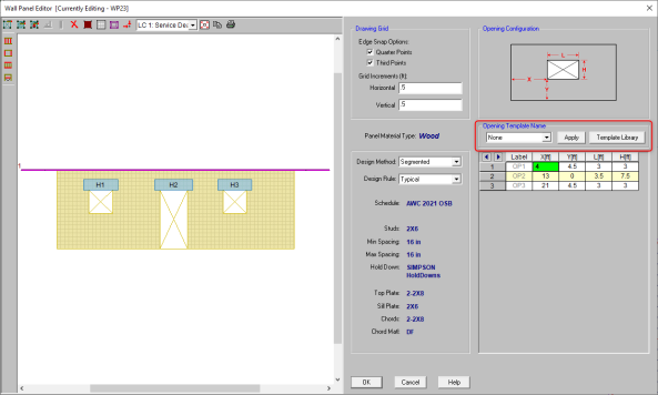
Click the Template Library button above the wall opening spreadsheet to add, delete, and modify wall opening templates. You can also access the Wall Opening Template Library dialog by clicking the  button on the toolbar.
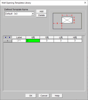
After creating new templates, you can select the template from the drop-down menu in the Wall Panel Editor and click the Apply button to import a template into the current wall panel.
Note:
- If you have existing openings or regions when you apply a template, the program will erase the existing openings and regions and apply the openings defined in the template. A warning message will be displayed when you click Apply indicating this.
- Similar to the Wall Panel Editor spreadsheet, the program will display red text in the spreadsheet if there are openings that overlap. The invalid openings must be fixed in order to save the template.
Loading
Wall panels can be loaded either directly or indirectly from supporting other elements (other walls, columns, beams, etc.). Line loads and distributed loads can be applied directly to wall panels.